|
02/01/2007 |
|
|
|||||||||||||||||||||||||||||||||||||||||||||||||||||||||||||||||||||||||||||||||||||||||||
|
Toby Family Website
http//fp.tobyfam.plus.com |
|
|
|||||||||||||||||||||||||||||||||||||||||||||||||||||||||||||||||||||||||||||||||||||||||||
|
|
|
|
Observatory |
||||||||||||||||||||||||||||||||||||||||||||||||||||||||||||||||||||||||||||||||||||||||||
|
|
NEWS:: The observatory building has been assembled, See picture page |
||||||||||||||||||||||||||||||||||||||||||||||||||||||||||||||||||||||||||||||||||||||||||||
How it all startedIt all began back in 2000 when I complained that I hardly use the telescope due to set-up time. A week later I read an article about somebody making a dome and now observing a lot more. The seed was sown. The design intend was a classical round building with a rotating dome on top. As the project progressed changes have been made to that intend. As it stands now the building is still round, but the top is now more like the ESO Paranal buildings. To date (mid 2004) the lower building is almost ready, and the design for the top is ready. I want to thank Harichandra, Robert, Paul who helped me get the concrete from an inpatient concrete truck driver into the garden, you guys where amazing The designThe Pier and PadThe Pier is a large 150mm sqr steel section with a wall thickness of 15mm ! sourced from a local construction company. this is set into a 1 meter deep hole filled with concrete By strategically placing foam formers we where able to pour the pier base and the pad for the building at the same time Buildings wallsOn top of the pad is a single row of vertically placed bricks. The walls are made of 18mm ply arc's
which are glued together to form circles The circles are 36mm thick and have
rebates for vertical bars to hold them at the right height. Most home dome designs have the top sitting on wheels, and therefore have no or limited vertical upwards constrained for the dome. This was a major sticking point to me as a big storm could simply lift the top of the building. I had to find a way around it. After many sketches I came up with the
design that allowed for upwards constraining. As stated before the original design was
a round building with a classical dome, while looking at how others have made
the dome I stumbled onto the truncated icosahedron design. This was
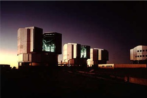
taken as easier as it only involves triangles. Again an article in a magazine triggered the solution Paranal observatory has round buildings with a truncated top seen head on it is square ad from the side it has a pent roof. This design also deals with another problem which I created. when we poured the pad, I was concerned that it may be to obtrusive in the garden, and therefore moved it out as far as possible to the fence. Later when I started making design drawings I realized that I needed space for the opened slit doors, which now would run into the fence. modifying the ESO design a bit, allowed for a door which is on the top only, and thus does not protrude. In order to come down low enough with the slit a simple slide door was designed Actual progressbelow is an sort of chronological report
on the progress and non progress of it all 03-03 got the bricks and mortar and the tubular ring in, the tubular ring is to be used as guide for laying the bricks 04-03 cut the base rings and created a framework from it, 05-03 applied the 9mm ply (amazing creaking noises) and created the door 06-03, Gwynedd born, learning to be a dad, so not much progress 08-03 still learning to be a dad but had some time to weld the strip to tubular ring, and machined wheels and plates 09-03 trial of tubular ring system.... problems The ring was not as flat as I though, as a result the top wheels when placed to close to the ring jam it. Further I had planned to drive the system using a friction drive made up out of a small motor and polyurethane wheel. The whole was not working, the ring would jam on 3 places when spun by hand. 10-03 five weeks past trying to solve the main drive issues. various ideas entered and went off the scene. Meanwhile I kept adjusting the wheels/ring set-up and improved the running of it considerably by splashing out on needle bearings. The dome rotation drive motor is a 40 rpm DC number, A 50mm drive wheel on a 2000mm ring makes for some fast moving, possibly to fast. a reduction has to be fitted so the motor is not running below stall speed when tracking the stars. Mid October Oops. in order to have some progress while the drive issues where dealt with, I decided to start installing the electrics. I wanted to have the inside walls as clean as possible, so the conduit to the pier had to cross the brick ring under floor level. This meant drilling a hole.....what happened is still a mystery, but the 21mm drill is bend, and 15 bricks are broken of the pad... So take wall section of the pad, refit the bricks... going backwards at a rate of knots. November...ground to a halt Some wiring finished, have working lights now, so even in the dark progress can be made. The next step is building the dome, so as I still had some doubts I made a list of risks involved in making a geodesic dome, against a simpler round disk design (like the ESO VLT building). The fact that the dome wall was so easy and that I was not getting exited about cutting the 105 triangles needed meant that the disk design won. So onwards , drawing work
March 2004 Work has taken almost all the time, the design for the top is done now, and some ring components have been cut September 2004 Started cutting the ellipse which will form the top section. have created a work area in front of the workshop so I can carry on even if it rains....If this all fits direct from the drawing I'll be amazed. two weeks until a Holliday will break up the project again... want to be constructed by then
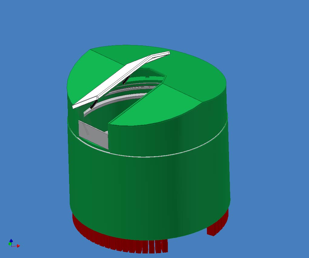
Nov 04 made progress, as pictures show the top is now nearly done, the slit door is made and skinned, as is the building door. some detail on the top building to be done and then the track in the lower building. Mid Nov 2004 The track issue is getting to me, the wheels operate fine, but having lifted the top I cannot see this being spun around with a friction drive. I feel that I need to be smart and design a positive engaged drive system like a chain.The chain can be fittted to the inside of the track, but that mean welding every link (say 15mm pitch that makes over 450 links), with the inherent danger of burning it trough if the chain is on the outside of the track then only a few welds are needed. but space is not there for the chain I think. further the track is not flat.....what are the costs of a new track custom made .... End Nov 2004 A lot has happened firstly My father in law was roped-in to transport 6 bicycle chains from Holland. these have been dully welded to the outside of the track. That was 480 tack welds in total, non burned trough the chain. in order to have the chain tight around the track, I decided to cut the track in two parts and allow the track to take up the slack The wheel plates have been cut in two pieces, so that the extra space allows for the chain. I finally made the decision on the covering. after many options ranging from PVC sheets, to Harwood, to state of the art PVC roofing materials (££££) I came back to good old GRP. The gear came in and I set of to use it. 1 long Tuesday for the top building , one long Sunday for the main building. one long Tuesday for flow-coating the building and a Sunday for flow-coating the top, and laminating the shutter door and entry door. The result is stunning and WHITE During the second removal of the building I have damaged the brick bottom row of the base. this has to be repaired. with the added problem that the building as away from the base. it is thus hard to check where the door opening starts......one step forwards.... Dec 04 all is laminated and bright white, the shutter door is fixed to the top, and the slide panel is fitted. The door is hung, and the bricks are back where they belong. Time to stack the lot just in time for Xmas
14 Dec 04 The evening before assembly of the observatory. have cleared out the site and check the weather several times. measured all, checked all, tested the tools......tomorrow morning 08.00 it all either happens or not. Dec 05 A whole year without much progress, In fact the list has grown again. It seems that rain water is running back into the building and being taken up by the internal wood. Thus need to tread the underside of the rotating part even further. As this is wet now, not much can be done. The only thing I can do is decide on the skirt design this has been a similar story as the weather proofing material decision, going backwards and forwards. The skirt is to be made of PU coated nylon coat material, which will have a large seam filled with lead on the bottom section sown in. The top edge is to be glued and folded over so it looks right. This should stop the rain coming in and allow the inside edge to dry, hopefully no lasting damage is done... The trick to get forward is to concentrate on the mechanical aspects as this is what stops progress at the moment. Early Nov 06, again a year gone with not much to show for a lot of effort has gone in trying to make the track run inside the building. unfortunately the dimensions have been taken to close so the track always scrapes the side. Eventually I came to the decision to get a new track made, which is a lot smaller in diameter. this should allow for more space for the roller, motor and thus work a lot simpler. A new ring has been made from 4x40x3mm and is now awaiting the new chain to be welded to. A design has been made with bottom wheels
with large flanges and top wheels which have no flange. This offset wheel design allows the chain to be mounted on one edge, and thus create more room for the motor with direct driven sprocket. with the current sprocket and chain length, a full rotation will take approximately 45 seconds.
17th Nov. progress.. Turned the 8 bottom wheels, and now set
to turn the shafts and top wheels. More importantly I figured out how to get the track inside the dome without lifting the top of the observatory off. This is going to safe me lots of time. As per Fermat I'm not telling though, in case it does not work. Is this the home straight ??? or yet another skylight in the tunnel 25th Nov. progress again Next placing the stands, and getting the
track inside on the rollers. Then I need to weld the top stands and create
the skirt. (PVC strip, sowing, weight) Only then we are ready for lifting the
top onto the track and seeing it all rotate (one hopes) Dec 3/4 The new track runs on the wheels quite
nice. The ring is about 20mm smaller then intended which means it can “ride”
from side to side. The downside to this is that it scrapes the large flanges
of the wheels. On Sunday I temp. propped up the top of
the building onto the track. After some missing screws where inserted it all
started to rotate which is a nice result.
Again the “riding” is proving to be an issue as with the weight of the top it
all runs a lot heavier then I want it to be. He solution will be a ring triangular in
section which nudges the track back. Instead of changing the wheels I am
going to turn rings and slide them over, in this way I can experiment. 500mm
of 50 diam. PVC is on its way which should give me 8 times to make it happen
??? The triangular rings work great, only 4 made to prove the idea and I can now turn it all by hand without it binding. A couple of things came about.
Good: Unknown:
Jan 02 Turned the remaining rings and fitted them, this now turns as smooth as it will be. Most of the drag seems to come from the improvised skirt which is tight around the building.
=========================================================== Control is likely to be designed around
the Pic 18F family with build in Ethernet controller.This seems by far the
simples route to IP based network. Some data: Microchip stack and footprint, Green is likely
to be used, blue is being debated
Therefore: Rom 6787 maxing to 7635 Ftp is usefull to send logfiles , or for
updates.. need to read more SPI Eeprom should not be needed as local eeprom is large enough (I think) reading again
|
|||||||||||||||||||||||||||||||||||||||||||||||||||||||||||||||||||||||||||||||||||||||||||||